Every screw is the same - or is it? If you think so, you risk worst-case scenarios like recalls, product liability claims, and personal injury. The VDI/VDE 2862 guideline brings clarity to screw joint analysis: it obliges assembly operations to systematically classify their tightening cases and to use suitable tools, inspection processes, and documentation measures for each category.
This article explains in practical terms what lies behind categories A, B, and C, which requirements apply to tools, MFU, and PFU in each case - and how you can correctly classify your types of screw joints in just a few steps using our interactive tool.
What is VDI/VDE 2862 - and who does it apply to?
VDI/VDE 2862 has applied to the automotive industry since 1999 and was extended in 2015 with Part 2 to cover all plant, machinery, and equipment manufacturers - which means it is now relevant for the entire assembly industry[1].
The guideline pursues a clear goal: it provides users with a binding framework for selecting tightening tools and ensures safe screw assembly in production. This is achieved through:
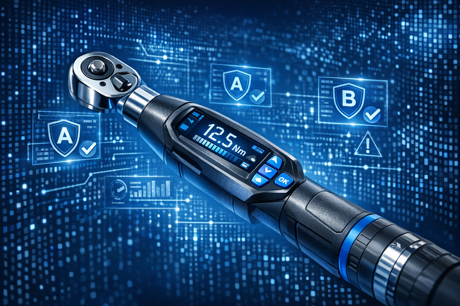
- Classification of screw joints into categories A, B, and C
- Definition of minimum requirements for tightening tools and systems for each category
- Specifications for error detection within each category
Product liability in the event of damage: Those who can prove that they have worked in accordance with VDI/VDE 2862 are considerably better protected in the event of product complaints or recalls. The guideline is regarded as state of the art - neglecting it can be regarded as gross negligence in the event of damage.
The guideline is regarded as state of the art in science and technology; in product liability cases, companies must be able to demonstrate that they have worked in accordance with this standard.
For anyone concerned with screw assembly quality, torque control, and assembly quality assurance, VDI 2862 is therefore a key reference document.
The three tightening case classes in detail
Classification into A, B, and C is based on the risk arising from failure of the joint as well as the ability to detect and prevent tightening errors during assembly.
Category A - Safety critical
Category A tightening cases involve a direct risk to life and limb or the environment if they fail. Typical examples include brake calipers, steering components, suspension parts, or safety critical joints in structural assemblies in aerospace.
This is where the strictest requirements apply for the tightening process: every individual tightening result must be monitored, documented, and traceable with appropriate tool monitoring. Faulty joints must be detected and blocked automatically. No component may leave the station without a validated OK result.
Category B - Function critical
If a category B joint fails, no personal injury occurs - but the product fails. In the automotive industry this is the classic "stranded vehicle": the vehicle loses an essential function. Gearbox, engine, or axle joints commonly fall into this category.
The requirements are noticeably lower than for category A, but still well above the basic minimum for assembly inspection and audit documentation: systematic documentation, regular machine capability evidence, and a robust process capability study (PFU) are mandatory.
Category C - Non critical
Category C tightening cases include all joints that are neither safety nor function critical - in the past also referred to as "customer critical" because a failure at worst only annoys the customer. Trim and cladding parts, attachments, or purely cosmetic joints are typical examples.
Here, simple or controlled tools such as basic torque wrenches or angle wrenches are permissible; documentation and random sampling are sufficient - but still advisable from a screw assembly quality perspective.
Requirements at a glance
| Feature | Category A - Safety-critical | Category B - Functionally Critical | Category C - Non-critical |
|---|---|---|---|
| Risk of failure | Hazard to life, limb & the environment | Functional failure / "Liegenbleiber" | Customer satisfaction affected |
| Examples | Brake caliper, steering, suspension | Gearbox, engine, suspension (secondary) | Covers, attachments, trim parts |
| Tool class | Controlled screwdriving subsystem with result feedback & fault shutdown | Controlled screwdriving subsystem with result feedback | Simple or controlled tool |
| Documentation | Full traceability of all screw data | Spot-check to full documentation | Not mandatory, recommended |
| MFU (Machine capability) | Mandatory, short intervals | Required, regular intervals | Recommended |
| PFU (Process capability) | Mandatory, tight tolerances (Cpk/Cmk ≥ 1.67) | Required (Cpk/Cmk ≥ 1.33) | Recommended, flexible framework |
| Error detection | 100% - automated detection & locking | Systematic check with feedback | Spot checks are sufficient |
Interactive: Determine your tightening case category
With the following tool, you can classify your tightening cases directly according to VDI/VDE 2862 in three steps:
This supports structured screw joint analysis and helps you choose the right assembly screws and torque control strategy for each category.
MFU and PFU: What is behind them?
In addition to the tool class itself, VDI/VDE 2862 requires proof of process reliability - on two levels:
MFU - Machine capability study
The MFU assesses the tightening tool itself: does it work with sufficient accuracy and repeatability across the whole tightening process? It is the basic prerequisite before a tool is released for safety or function critical joints. Machine capability must be checked regularly in accordance with VDI/VDE 2645 Part 2[2].
PFU - Process capability study
The PFU goes one step further: it evaluates the entire tightening process under real production conditions - including material, operator, environment, and tool condition. Joints that are actually not OK but are incorrectly flagged as OK must be reliably detected by a PFU. For category A, process capability indices of Cpk/Cmk ≥ 1.67 are typically expected; for category B, Cpk/Cmk ≥ 1.33 is considered the minimum requirement.
For an in-depth look at calculation methods, Cpk/Cmk, and the step-by-step execution of a process capability study, we recommend our guide: PFU according to VDI/VDE 2645-3: Step-by-step guide
Accurate torque analysis, supported by suitable torque control tools, is essential here to achieve reliable PFU results.
From standard to practice: How to implement VDI/VDE 2862
Implementing the guideline does not have to be an uphill struggle - provided it is approached in a structured way:
1. Analyse and classify tightening cases
Work together with design and quality management to review all joints. Use the interactive tool above as a starting point. Any doubts between categories A and B should always be resolved in favour of the higher category.
2. Check tools for suitability
The guideline does not prescribe which specific tool must be used[3] - but it clearly defines which properties (measurement, feedback, error shut-off) are required for each category. For categories A and B, this means in practice: electronically controlled, measuring tools with data interfaces for precise torque control and angle monitoring, such as modern torque wrenches and angle wrenches.
3. Perform and document MFU and PFU
Ensure that your tools are regularly checked for machine capability and calibrated. For categories A and B, this evidence is not optional, but compulsory, and forms a key part of your assembly quality assurance and audit documentation.
4. Ensure documentation and traceability
Especially for category A joints, the rule is: all tightening data must be available and documented[3]. Part identification and automated error detection are sensible additions that improve tool monitoring and overall assembly inspection.
How GWK supports you in achieving compliance
The requirements of VDI/VDE 2862 are directly embedded in GWK products and services designed for torque analysis and tightening process control:
QUANTEC MCS® - Analysis tool for categories A and B
QUANTEC MCS® measures torque, angle, and yield point with an accuracy of ±1% between 10 and 100% of the nominal range and enables direct execution of process capability studies in accordance with VDI/VDE 2645-3. All tightening data is stored completely and can be transmitted via WLAN to the analysis and archiving software Ceus or QS-Torque - fully auditable and ideal for screw assembly quality and audit documentation.
Q-CHECK® - Precise residual torque measurement for PFU
Q-CHECK® was developed specifically for residual torque measurements and process capability studies - compliant with VDI/VDE 2645-3. With 2 GB of memory for up to 1,000 tightening points, it provides the measurement data you need to demonstrate PFU compliance for category A and B joints and to verify the quality of your tightening process.
DAkkS-accredited calibration laboratory & mobile service
GWK operates its own DAkkS-accredited calibration laboratory with class 0.2 accuracy. Mobile calibration services carried out directly on site minimise downtime and ensure the continuous availability of your production equipment. This is particularly important, as MFU requires regular calibration cycles for all relevant tightening tools.
OPERATOR® - Production tools with traceability
The modular OPERATOR® tools with their innovative interchangeable square drive system enable flexible production assembly with integrated data capture - providing an end-to-end quality chain from analysis report to final tightening result for all relevant types of screw joints.
Conclusion: Classification as the basis of every safe tightening process
Tightening case classification according to VDI/VDE 2862 is not a mere bureaucratic exercise - it is the foundation of safe, efficient, and legally secure screw assembly. Anyone who consistently classifies their joints into A, B, and C not only selects the right tools for torque control and tool monitoring: they also create the basis for demonstrable quality, secure audits, and minimised liability risks in screw assembly quality.
Use the interactive classification tool above as your starting point - and contact us if you need support in implementing the guideline in your specific production environment or in optimising your assembly screws and tightening process.
Who is responsible for the screw-joint classification?
Classification is primarily the responsibility of the design department. Already in the development phase the screw joint is evaluated, and the classification must be passed to production. If there is any uncertainty between Category A and B, it is advisable to involve specialists.
Does VDI/VDE 2862 also apply to my operation outside the automotive industry?
Yes. Since the expansion through Sheet 2 in 2015, the directive also applies to plant, machinery and equipment construction as well as to flange connections on load-bearing components. It is relevant for all assembly operations that cannot demonstrate the process safety of their screw assembly through their own equivalent process.
What is the difference between MFU and PFU?
The MFU (Machine Capability Investigation) checks whether the screw tool itself operates with sufficient accuracy and repeatability – i.e., the tool quality. The PFU (Process Capability Investigation), on the other hand, evaluates the entire screw process under real conditions, including material, personnel and environment. Both verifications are mandatory for Category-A connections.
Which tool class do I need for Category-A screw joints?
For safety-critical Category-A connections, the VDI/VDE 2862 requires the use of a controlled screwdriving system with full result feedback and automated fault shut-off. The tool must be able to directly measure and document torque and/or rotation angle.
How does the QUANTEC MCS® support standard implementation?
The QUANTEC MCS® from GWK measures torque, rotation angle, and yield strength with ±1% accuracy and directly enables process capability testing according to VDI/VDE 2645-3. All data are recorded seamlessly and can be transmitted via WLAN to the Ceus or QS-Torque software - for a fully auditable quality chain.