

Modern commercial aircraft derive more than half of their structural weight from lightweight materials. According to Airbus, 53% of the A350 XWB's total weight consists of carbon fiber reinforced polymer (CFRP), [1] and the Boeing 787 Dreamliner is likewise built from roughly 50% composite structures. [2] Titanium fasteners and CFRP components are no longer the exception in this world - they are the standard.
Yet this very material combination creates fastening challenges that conventional tightening methods simply cannot handle. Relying exclusively on torque specifications risks delamination, galling, or a clamp load that falls well outside the permissible window. This article explains why - and which measurement technology provides the answer.
CFRP in Bolted Joints: Three Risks Every Design Engineer Must Know
1. Delamination from Excessive Bearing Stress
CFRP is extremely strong along the fiber direction - but behaves in a fundamentally different way perpendicular to it, i.e., through the thickness. In fiber-reinforced polymer components under the closed load path of a preloaded bolted joint, the dominant failure modes are typically not classical bolt fracture, [3] but rather localized laminate damage in the form of delamination or inter-fiber failure.
The allowable bearing stress under the bolt head is significantly lower for CFRP laminates than for metallic materials. Research from the Bundeswehr University Munich, using acoustic emission measurements, identifies a maximum allowable bearing stress of 140 N/mm² for thermoset CF laminates. [4] For comparison, steel tolerates many times that value. Exceeding this limit causes permanent laminate damage - often with no visible external indication.
The implication for assembly: washers with a defined bearing surface are mandatory, and the actual clamp load introduced must be precisely controlled. An excessive tightening torque is not a safety margin here - it is a damage mechanism.
2. Settling Behavior and Preload Loss Due to Creep
Preload loss in CFRP bolted joints is influenced by the creep behavior of the laminate in the through-thickness direction. [4] The resin matrix system yields under sustained compressive loading - an effect that continues over hours and days and intensifies with temperature.
Settling refers to the smoothing of surface roughness at component and interface surfaces as well as at the fastener elements themselves. [5] Creep, on the other hand, can produce far greater preload losses that develop over a considerably longer period. For aerospace applications, this means the residual clamp load after settling must be demonstrably sufficient for all load cases - a requirement that cannot be met without reliable measurement data from the fastening process.
3. Friction Scatter Makes Pure Torque Control Unreliable
This is the core problem: the preload resulting from an applied torque is heavily influenced by varying friction coefficients and the torque scatter of the tightening tool. [6] A distinction must be made between friction under the bolt head and friction in the thread engagement.
The combined effect of these varying friction influences means that even with high torque repeatability, variations in the resulting preload of 50% or more can occur. [7] In CFRP joints - where the tolerance window between "too little clamp load" (joint failure) and "too much clamp load" (delamination) is already narrow - this level of scatter is unacceptable.
Critical tolerance window in CFRP: In CFRP joints, the margin between insufficient clamping force and surface pressure that damages the laminate is often razor-thin. Pure torque tightening cannot reliably hit this window — friction scatter is simply too large.
Titanium: Lightweight, Corrosion-Resistant - and Treacherous to Tighten
Titanium fasteners are indispensable in aerospace thanks to their outstanding combination of strength and low weight. Titanium is stronger than steel and nearly as light as aluminum, [8] making it the preferred fastener material in CFRP structures.
But titanium brings a specific risk: galling, also known as cold welding. Galling occurs when metal surfaces come into very close contact under pressure and the resulting friction damages the passivating oxide layer at the surface, allowing cold welding to take place. [9] In titanium, this effect is particularly pronounced because the natural titanium oxide layer is mechanically abraded during tightening, bringing bare metal surfaces into direct contact.
The result: the fastener can no longer be removed - or fractures during the attempt. In aerospace, where maintainability and defined disassembly are safety-critical requirements, this is a serious problem.
Why Titanium Further Increases Friction Scatter
Compared to coated steel fasteners, titanium screws exhibit a higher and - more importantly - less consistent coefficient of friction. Lubricants or coatings intended to prevent galling significantly alter the friction conditions, and with them the relationship between applied torque and actual preload. Lubricants and thread-locking compounds reduce the friction coefficient between the threads, which means the tightening torque must be adjusted accordingly. [10]
For the assembly technician, this means the specified torque value alone says very little about whether the desired clamp load has actually been achieved. The joint must be analyzed - not just tightened.
The Solution: Torque-Angle Analysis with the QUANTEC MCS®
The angle-controlled tightening method directly addresses the fundamental weakness of pure torque control. From the point at which angle-controlled tightening begins, the fastener is tightened independently of friction; the resulting total preload scatter is therefore lower than with a purely torque-controlled tightening method. [7]
The physical rationale: axial force is proportional to torque - elongation is proportional to rotation angle. [6] By tracking the rotation angle, bolt elongation - and therefore clamp load - can be set far more accurately and reproducibly than with torque alone. Friction variations in the thread that would distort a pure torque method play a significantly smaller role in angle-based tightening.
Reference-Point-Free Angle Measurement: The Critical Difference
Conventional angle measurement requires a fixed reference point on the component - a requirement that is often impractical, especially for hard-to-access joints in aircraft structures. The QUANTEC MCS® analysis tool from GWK solves this problem with its reference-point-free angle measurement: the angle is captured directly at the tool, with no external reference required.
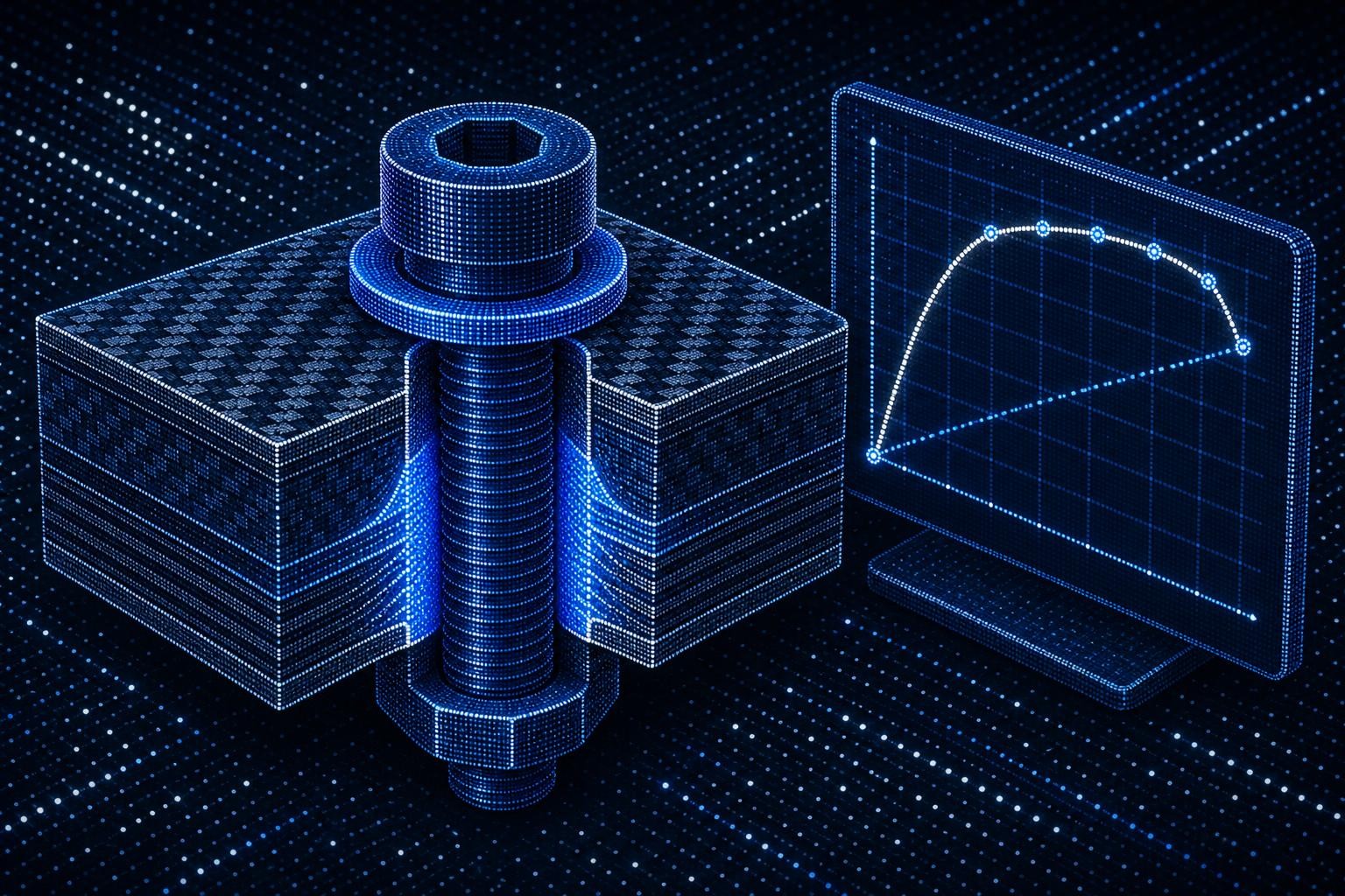
The result is a complete torque-angle diagram for every individual tightening operation. This diagram reveals:
- The tightening zone: A linear curve rise indicates that the joint is behaving elastically and correctly.
- Anomalies in the tightening curve: Irregularities in the curve profile point to settling effects, friction spikes, or the onset of galling - while tightening is still in progress.
- Yield point detection: The inflection point in the torque-angle curve is clearly identifiable, preventing both under-tightening and over-tightening.
- Batch-to-batch comparability: Multiple tightening operations can be overlaid and statistically evaluated - the foundation for process capability studies per VDI/VDE 2645-3.
 AI-generated image
What the QUANTEC MCS® Delivers in Practice
The QUANTEC MCS® analysis tool is the compact bolt lab for development and quality assurance. With its rugged aluminum-titanium construction and a measurement accuracy of ±1% between 10 and 100% of the rated range, it delivers the data quality required for safety-critical aerospace fastening applications.
For CFRP/titanium joints specifically, this means:
| Challenge | Risk Without Analysis | Solution with QUANTEC MCS® |
|---|---|---|
| Friction scatter with titanium | Preload ±50% of target value | Angle-based evaluation independent of friction |
| Delamination from over-tightening | Laminate damage, not visible | Clamp load upper limit monitorable |
| Galling | Fastener irremovable, fracture risk | Anomaly in curve profile detectable early |
| Settling behavior | Preload loss after assembly | Settling behavior quantifiable, re-tightening strategy derivable |
| Documentation requirements | No traceability | Complete curve documentation, WLAN data transfer |
Compatibility with QuanLab Pro® and QS-Torque enables seamless archiving of all fastening data - a requirement that is non-negotiable in aerospace.
See torque-angle analysis in action on your specific CFRP/titanium bolted joint — at the GWK lab or directly at your facility.
Request a QUANTEC MCS® Live DemoProcess Validation: From Individual Test to Reproducible Series Production
Torque-angle analysis with the QUANTEC MCS® is not just a development tool - it is the foundation for process validation in series assembly.
Recording of the complete torque-angle diagram under real-world conditions: material, surface condition, lubricant, and tightening speed. Identification of friction classes and settling behavior.
Derivation of the optimal tightening window: minimum clamping force (joint function) and maximum clamping force (delamination limit for CFRP). Definition of torque and angle-of-turn limit values.
Statistical evaluation of multiple tightening operations in accordance with VDI/VDE 2645-3 using the Q-CHECK® QS and audit tool. Verification of process capability for series production.
Deployment of the OPERATOR® production tool with Wi-Fi data transmission and PLC communication (OPERATOR® EST01) for seamless documentation of every joint on the line.
Regular verification of tool accuracy through DAkkS-accredited calibration — either at the GWK stationary lab or on-site at the customer's facility.
Why Pure Torque Control Is Not Enough in Aerospace
Torque-controlled tightening has become the standard in many industries because of its ease of use. But the torque method is typically designed to load fasteners to only 60 to 70 percent of their capacity, to avoid shearing them off if friction happens to be higher than expected. [11] This deliberate under-utilization is not an option in aerospace: every gram counts, and every joint must perform its full function.
There is a further complication: approximately 90% of the applied torque is consumed overcoming friction, [12] with only a small fraction actually generating the desired preload. When friction conditions vary - as they do with titanium fasteners used with and without lubricant - the resulting clamp load becomes nearly impossible to predict.
Torque-angle analysis closes this gap: it makes the fastening process transparent, reproducible, and auditable.
Conclusion: Lightweight Construction Demands Measurement Technology That Keeps Pace
CFRP and titanium have transformed the performance of modern aerospace structures. Fastening technology must keep up with this evolution. The narrow clamp load window in CFRP laminates, the galling risk with titanium fasteners, and the pronounced settling behavior of both materials cannot be managed with torque-only tightening.
Torque-angle analysis with the QUANTEC MCS® - based on reference-point-free angle measurement - provides the data foundation required for safe, reproducible, and fully documented lightweight joints in aerospace. Not as an added burden, but as an integral part of a validated fastening process.
Talk to our experts about your CFRP or titanium joint. We'll analyze your bolted connection and show you how to reliably verify clamping force and process integrity.
Request a Free Bolting Process Analysis